AIR INFILTRATION: ADVANCED
- Omer T. Karaguzel

- Oct 13, 2021
- 7 min read
Updated: Oct 25, 2021
According to ASHRAE 90.1 (2016/2019) energy standard, the envelope air infiltration characteristics in energy models should account for dynamic changes in weather (wind speed effects) and building operation profiles (HVAC system effects). These changes are required to be “dynamic” since they should be reflected to the building energy model at each simulation time step. HVAC system behavior (such as positive pressurization measures) can be reflected on the air infiltration modeling by coupling the peak infiltration rate input with a dynamic (~ simulation time step-based) operational schedule/profile. This is the infiltration rate profile defined by the user.
A common assumption which is also used in the U.S. DOE’s reference commercial building energy model sets is to reduce the infiltration rate down to 25% of the peak level during times of HVAC operations for set-point temperature controls (~during the office hours) and assume the peak rates during times of HVAC operations for set-back controls (~during the non-office hours). Such an operational profile reflects the assumption that during full HVAC operation, the infiltration rates are cut by 75% due to the positive pressurization of the building spaces and the rates are back to 100% level when system is nonoperational (at the main AHU level since set-back temperatures can be controlled by the terminal-level devices without a need to energize the primary supply and return fans).
Another important point mentioned in the standard is that infiltration rates should be modeled using the same methodology and the initial air leakage rate for the BASELINE and the PROPOSED design cases. However, this rule can be excepted in case a whole-building air leakage testing (according to ASTM E779) have been conducted for the PROPOSED design case after the construction. In such a case, the PROPOSED design case model can assume the measured infiltration rates instead of the standard (air leakage) rates which is already assumed for the BASELINE case model. The question is what is the standard air leakage rate to define envelope air infiltration for the BASELINE case models (which should be the same for the PPOPOSED design case model unless there are measures available)?
ASHRAE 90.1 standard has the information and states that the air leakage rate of the building envelope (I75Pa) at a fixed pressure differential of 0.3in. of water (~ 75 Pascals) should be 0.4 cfm/ft2 (2.032 l/s/m2). This statement indicates the peak air flow rate (in cfm or l/s) through unit area (ft2 or m2) of a building envelope when there is an unchanging pressure differential of 0.3in. water or 75Pa between the inside spaces and the outside environment. And then comes the big question. How can we convert this rate of envelope leakage to the appropriate units (or parameters) so that they can be useful for the simulation program to build a model with the required infiltration rates? Here is the answer that is also mentioned in the ASHRAE 90.1 standard in Section G3.1.1.4 Modeling Building Envelope Infiltration.
The standard offers three methods of conversion which are (1) Floor Area Method, (2) Above-Grade Wall Area Method, (3) Measured Data Method.
(1) Floor Area Method
This method offers the following equation for the conversion of the standard air leakage rate (I75Pa) to the adjusted air leakage rate of the building envelope relative to the gross floor area (IFLR).

In this equation, “I75Pa” is already given as 0.4 cfm/ft2 (2.032 l/s/m2) which is the air leakage rate of the building envelope at a fixed building pressure differential of 0.3in. water (~75Pa). “IFLR” is the adjusted rate of air leakage relative to the gross floor area at a reference with speed of 10mph (4.47m/s) which can be entered into the building energy model. “S” is the total area of the building envelope (ft2 or m2) which includes the lowest floor, any below-grade walls, above-grade walls, and the roof. S also includes the vertical fenestration (~windows) and the skylights. “AFLR” is the gross floor are (ft2 or m2). To find out IFLR, we need to find the total building envelope area (which includes all the external bounding surfaces) and then divide it by the gross floor area of the building and multiply this ratio with the standard 0.4 cfm/ft2 number and with a constant of 0.112 as given in the equation.
(2) Abode-Grade Wall Area Method
This method is for simulation programs that accepts infiltration rates as flow rate per unit above-grade wall area and this method offers the following equation for the conversion of the standard air leakage rate (I75Pa) to the adjusted air leakage rate of the building envelope relative to the area of the above-grade walls (IAWG).

This equation is very similar to the one already mentioned for the (1) Floor Area Method. I75Pa = 0.4 cfm/m2 is already given. “S” is the total area of the building envelope (including all the building surfaces with fenestration and skylights – if any). S is divided by the “AAGW” which indicates the total area of above-grades walls of the building envelope (ft2 or m2). To find out IAGW, we need to first identify the total building envelope area (S) and the divide it by the total area of above-grades walls of the building envelope (AAGW) and then multiply this ratio with the standard air leakage rate (I75Pa) and with a constant of 0.112 as given in the equation.
(3) Measured Data Method
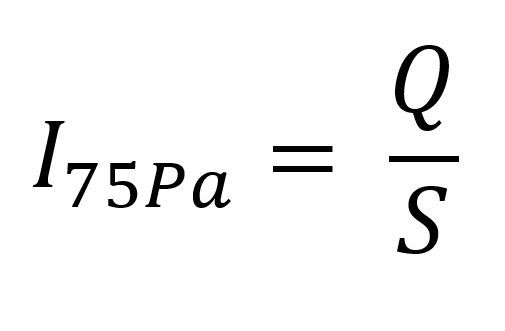
This method is not used during the design stage building energy modeling activities because it relies on site data of infiltration rate measured according to ASTM E779 after the construction phase of the building project. In case, any measured data available, the following equation can be used to find the I75Pa which will be used for the PROPOSED design case model instead of assuming the standard 0.4 cfm/ft2 value (which is already needed for the BASELINE design case model). Therefore, this method and the equation given here offers an alternative value of I75Pa which can be entered into the equations suggested by (1) Floor Area Method, and (2) Above-Grade Wall area method.

This equation simply requires “Q” to be divided by “S” to find out measured data dependent I75Pa value. “S” was already mentioned above as the total area of the building envelope. “Q” which is the new term here is the volume of air (in cfm) flowing through the building envelope when it is subjected to a pressure difference of 0.3in. water (75Pa) according to the specifications of the ASTM E779 standard.
In sum, what is our take from this summary?
1. In case measured infiltration data is not available, the PROPOSED design model and the BASELINE design model SHOULD assume the same standard air leakage rate of I75Pa which is already given in the ASHRAE 90.1 standard as 0.4 cfm/ft2 (2.032 l/s/m2).
2. Air infiltration simulations should be dynamic (re-calculated at each simulation time step). This is already satisfied when doing energy modeling with a dynamic simulation program.
3. Air infiltration simulations should consider wind pressure effects. This is also satisfied internally by most of the dynamic simulation programs such as IESVE or Design Builder.
4. Air Infiltration simulations should consider the HVAC operation effects to consider the positive pressurizations. This can be satisfied by coupling the peak infiltration rate with an hourly fractional operational profile to adjust it during set-point and set-back times HVAC operation (also known as 25%-rule or 25%-profiling).
5. I75Pa cannot be directly entered into the simulation program. It should be converted/adjusted using methods which requires the standard I75Pa along with S (the total envelope area) and AAGW (total above-grade wall area) and the constant term of 0.112.
6. The energy modeler needs to analyze the geometric model at hand to extract out “S” and “AAGW” and then execute the simple equations and find out “IFLR” or “IAGW” and enter these values to the simulation program as needed.
7. In case measured infiltration data is available, the energy modeler has the freedom to re-calculate the I75 instead of using the standard rate of 0.4 cfm/ft2. The actual I75Pa data can be used to update the PROPOSED design case model while leaving the BASELINE design case model at the standard level. This can be used to quantity an energy conservation measure due to airtight envelope which shows reduced levels of air leakage. To find the new I75Pa the (3) Measured Data method can be used which requires site data and the “S” which is the total building envelope area. Using the new I75Pa the required IFLR and IAGW can also be calculated which would be different from the BASELINE design case model.


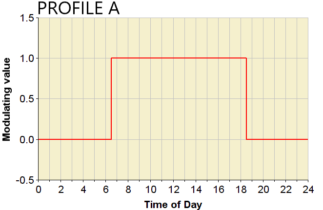
Here you see two different profiles. The Profile A is controlling the HVAC system operation by indicating the time when temperature controls shift from set-point to set-back hours and the one on the Profile B the infiltration rate schedule developed according to the 25%-rule. These two profiles are inversely related to each other such that when ever Profile A indicates the set-point temperature hours between 6:30am and 18:30am with a value of 1.0, the Profile B indicates a fractional value of 0.25 (25%) (between the same period) to be applied to peak infiltration rate inputs. On the other hand, when Profile A indicates the set-back temperature hours (with the value of 0.0) between 18:30 to midnight (24) and from midnight to 6:30am in the morning, the Profile B in dictates a fractional value of 1.00 (100%) (between the same period) also to be applied to peak infiltration rate inputs. This profile set up can be used to model the dynamic changes in the air infiltration rates due to the operation of the HVAC systems creating positive pressure conditions for the building spaces which reduces the infiltration rates down to 75% of maximum when compared to the times when systems are not operational (at the main AHU level).
Finally, I find it important to mention here that even though not mentioned in the ASHRAE 90.1 standard, it would be a good practice NOT to assume any infiltration rates for the CORE thermal zones of building energy models. By CORE thermal zone, I am referring to the BEM spaces that have no exposed surface to the outside environment (i.e., completely encapsulated by the perimeter BEM spaces exposed to outside). For such spaces, infiltration rates can be reduced to 0.0 cfm/ft2 (l/s/m2) or a fractional profile with 0.0 modulating factor for all hours can be coupled with the default infiltration rate inputs (irrespective of their magnitude) (e.g., “off continuously” profile).
Please have a look at the excel-based calculator that can help with the calculations given above (Air-Leakage-Adjustment-Calculator.xlsx)
Omer T. Karaguzel, PhD

Comments